
Raspberry Pi Push Button Input with Hardware and Software Debouncing
This experiment implements a reliable push‑button input for a Raspberry
Pi.
The design combines hardware debouncing with software debouncing
to produce stable digital input signals.
The circuit output connects to a Raspberry Pi GPIO pin that reads 0 V
(LOW) and 3.3 V (HIGH).
Components
Required hardware:
- Raspberry Pi board (any version). Example used: Raspberry Pi 3
Model B - Tactile push button
- Resistors:
- 1 kΩ
- 10 kΩ
- Capacitor: 0.1 µF (100 nF)
- Schmitt Trigger IC: SN74HC14N
- Breadboard
- Jumper wires (female‑to‑male)
Button Driver Circuit
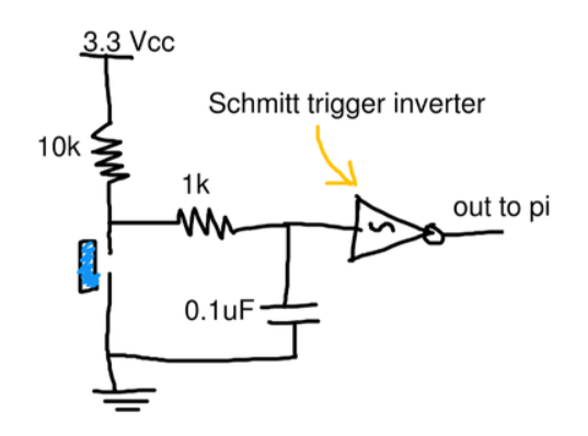
The circuit output connects to a Raspberry Pi GPIO input.
The Raspberry Pi provides:
- 3.3 V for logic HIGH
- GND for logic LOW
These supply rails are sourced directly from the Pi.
GPIO Connection
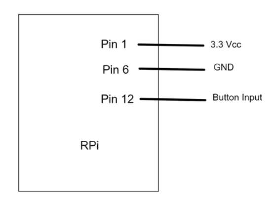
Key detail:
- Button output → Pin 12
- Pin 12 → BCM GPIO 18
The software must reference GPIO 18.
Power Considerations
The Raspberry Pi 3.3 V and 5 V rails come directly from the
power adapter.
The official Raspberry Pi adapter provides up to 2.5 A, which is
sufficient for small external circuits.
However:
- Always calculate current draw
- Verify component limits
- Avoid overloading the Pi power rails
Software Implementation
Several languages support Raspberry Pi GPIO control.
Python is commonly used due to its readability and mature libraries.
Example implementation using RPi.GPIO.
#!/usr/bin/python

import RPi.GPIO as GPIO
import time

GPIO.setwarnings(False)
GPIO.setmode(GPIO.BCM)

BTN_PIN = 18

# Configure input
GPIO.setup(BTN_PIN, GPIO.IN)

def btn_callback(channel):
    if GPIO.input(BTN_PIN):
        print("Button was pressed.")

input("Press Enter when ready
>")

# Detect rising and falling edges
GPIO.add_event_detect(
    BTN_PIN,
    GPIO.BOTH,
    callback=btn_callback,
    bouncetime=100
)

try:
    while True:
        time.sleep(1)

except KeyboardInterrupt:
    GPIO.cleanup()

GPIO.cleanup()
Hardware Debouncing
Mechanical buttons produce rapid voltage oscillations when pressed
or released.
These oscillations create false transitions.
The hardware debounce circuit:
- Filters noise
- Smooths voltage transitions
- Produces a stable digital signal
Why Use a Schmitt Trigger
The SN74HC14N Schmitt trigger further stabilizes the signal.
It uses hysteresis, meaning:
- One threshold for LOW → HIGH
- Another threshold for HIGH → LOW
This prevents rapid toggling caused by noisy signals and slow voltage
transitions.
Software Debouncing
The GPIO library also implements software debouncing.
Mechanism:
- Multiple reads of the GPIO input
- Each read separated by the configured bounce time
- State change is confirmed only if the signal remains stable
Example logic for detecting a rising edge:
0 V → 3.3 V → 3.3 V
Each read occurs 100 ms apart.
Short spikes (e.g., 3.0 V for 30 ms) are ignored.
Choosing a Bounce Time
Bounce duration depends on the mechanical properties of the button.
Typical values:
- 50--100 ms
Empirical testing is recommended to determine the optimal value.
Result
The circuit produces a stable push‑button input for Raspberry Pi
GPIO.
This pattern is reusable for:
- User input interfaces
- Control panels
- Embedded interaction systems
Future circuits can reuse this button interface as a reliable input
module.
Member discussion: